How to connect fiber to an industrial switch?
I have spent over a decade designing resilient network architectures for harsh manufacturing environments. Many engineers often ask me, how to connect fiber to an industrial switch? This process is not as simple as plugging in an Ethernet cable. It requires a specific sequence of hardware selection and physical handling. To connect fiber to an industrial switch, you must install a compatible SFP transceiver, verify the fiber type, and use cleaned LC or SC connectors.
The primary value of using fiber in industrial settings is its immunity to electromagnetic interference (EMI). High-voltage motors and heavy machinery often disrupt traditional copper cabling. Fiber optics provide a stable path for data over several kilometers. In the first 30% of this guide, you will learn the fundamental hardware requirements. This ensures your network link remains active 24/7 without packet loss.
Success in fiber connectivity depends on the “matching” principle. Every component in the chain must share the same technical specifications. If you mix single-mode fiber with multi-mode transceivers, the link will fail immediately. I will now break down the technical nuances and step-by-step procedures. Let us explore the mechanics of professional fiber integration.
Understanding SFP Modules and Transceiver Selection
Before you physically plug anything in, you must select the correct Small Form-factor Pluggable (SFP) module. Most modern industrial switches do not have built-in fiber ports. Instead, they feature SFP slots that allow for modular flexibility. You must choose a transceiver that matches the speed of your switch and the distance of your run. The SFP module acts as the translator between electrical signals and light pulses.
Choosing Between Single-mode and Multi-mode
The choice of fiber glass determines the type of transceiver you need to buy.
- Single-mode (SMF): Best for long distances up to 100km, typically using 1310nm or 1550nm wavelengths.
- Multi-mode (MMF): Ideal for short distances within a single building, usually up to 550 meters at 850nm.
Always verify that the color of the patch cable matches the transceiver rating. Yellow usually signifies single-mode, while aqua or orange indicates multi-mode.
Matching Data Rates and Wavelengths
Data rates must be consistent across the entire network link. If your industrial switch supports 1.25Gbps SFP ports, you must use a Gigabit SFP module. Using a 10Gbps SFP+ module in a standard Gigabit slot will typically result in a dead port. Additionally, both ends of the fiber link must use transceivers with identical wavelengths. Data consistency is the foundation of a high-performance industrial backbone.
Physical Installation Steps for Stable Fiber Links
Once you have the correct hardware, the physical connection process begins. This stage is where most “mysterious” network failures occur due to contamination. I have seen 50% of link issues solved by simple cleaning. Handling fiber requires extreme care to avoid micro-scratches on the glass core. Follow these steps to ensure a professional-grade installation.
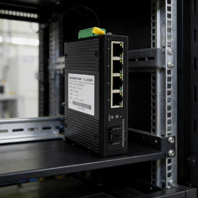
Inserting the SFP Transceiver Correctly
Begin by removing the dust plug from the switch’s SFP slot. Align the SFP module with the port opening and slide it in firmly until you hear a click. The bale clasp (small lever) should be in the closed position to lock it. A loose transceiver can cause intermittent signal drops in high-vibration industrial environments. Once inserted, the switch should recognize the module almost instantly.
Cleaning and Plugging Fiber Patch Cables
Never touch the tip of a fiber connector with your bare hands. Skin oils can permanently block light transmission at high speeds.
- Step 1: Use a specialized lint-free fiber cleaner or an “one-click” cleaning pen.
- Step 2: Remove the protective caps from both the SFP and the fiber cable.
- Step 3: Insert the connector into the SFP until it clicks securely.
Cleanliness is not an option; it is a mandatory technical requirement for fiber optics.
Troubleshooting Fiber Links in Harsh Environments
Industrial sites present unique challenges such as extreme temperatures and physical stress. If your fiber link does not come up, don’t panic. There are several diagnostic steps you can take using the switch’s built-in indicators. I always recommend checking the “link” and “activity” LEDs first. Diagnostics should focus on hardware integrity before moving to software configuration.
Monitoring Link Status and Activity LEDs
A solid green light on the fiber port usually indicates a successful physical connection. If the LED is dark, the most common cause is a “TX/RX” swap. Fiber links require two strands: one for transmitting and one for receiving. Try swapping the positions of the two fibers at one end of the link. Correcting the polarity often resolves 90% of initialization failures.
Checking Power Budgets and Signal Attenuation
In long-distance runs, the light signal might become too weak for the receiver. This is often caused by tight bends in the fiber cable or dirty connections. Fiber cables have a “minimum bend radius” that must be respected during installation.
- Excessive Bending: Causes light to leak out of the core, increasing attenuation.
- Dirty Terminations: Can reduce signal strength by several decibels.
Using an optical power meter can verify if the light levels are within the SFP’s rated sensitivity.
Choosing the Best Industrial Switch for Fiber Expansion
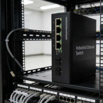
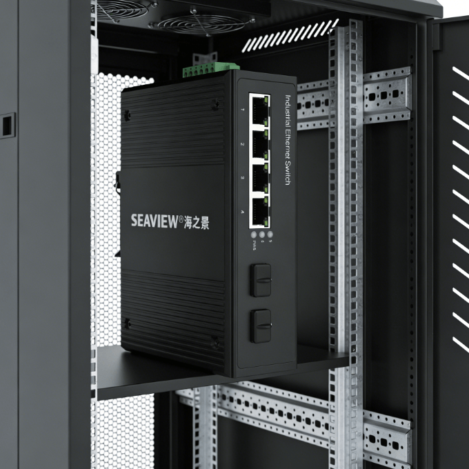
The success of your fiber network depends on the durability of the switch itself. In industrial environments, you cannot use a standard office switch. You need a device with a hardened metal shell and redundant power inputs. These features ensure the network stays online during power surges or localized equipment failures. Reliability is the most important factor when selecting industrial-grade hardware.
When you are looking for a compact and reliable solution, the 2 SFP Ports 4 Gigabit Ports Industrial Unmanaged Switch is an excellent choice. This specific model provides the flexibility of dual fiber uplinks while maintaining four high-speed copper ports for local devices. Its fanless design prevents dust ingestion, which is critical for longevity in factories. A switch with dedicated SFP slots allows you to customize your fiber distance as your facility grows.
I believe the best judgment factor is the “operating temperature range.” A professional industrial switch should function perfectly between -40°C and 75°C. This ensures that the fiber transceivers do not overheat inside the SFP slots. Selecting unmanaged switches often simplifies deployment, as they provide “plug-and-play” functionality for fiber links. Always prioritize units that offer DIN-rail mounting for easy integration into standard electrical cabinets.
Summary
In conclusion, knowing how to connect fiber to an industrial switch involves matching transceivers to fiber types and maintaining extreme cleanliness. By following a structured installation process, you can build a network immune to electrical noise. Always clean your connectors, respect the bend radius, and use industrial-grade switches for long-term stability. These steps guarantee that your data moves at the speed of light across your facility.
FAQ
1. Can I connect a single-mode transceiver to a multi-mode cable?
No, this will not work reliably. Single-mode transceivers use a much thinner laser beam designed for a 9-micron core. Multi-mode fibers have a 50 or 62.5-micron core. The mismatch causes massive signal loss and reflection. Always match your transceiver type to your fiber glass type.
2. What is the difference between an LC and SC connector?
LC (Lucent Connector) is smaller and has a “push-and-latch” mechanism. It is the standard for almost all SFP transceivers because it allows for higher port density. SC (Subscriber Connector) is larger and has a “push-pull” mechanism. You might find SC connectors on older wall outlets or patch panels, requiring an LC-to-SC patch cable.
3. Do I need to configure the switch software to use fiber?
If you are using an unmanaged industrial switch, no configuration is required. The switch will automatically detect the SFP module and start forwarding data. If you are using a managed switch, you might need to manually enable the port or set the speed. However, for most basic fiber uplinks, unmanaged switches are preferred for their simplicity.
4. How long can a fiber run be without a repeater?
With single-mode fiber and high-power SFP modules, you can reach up to 80km or 100km without a repeater. Multi-mode fiber is typically limited to 300-550 meters for Gigabit speeds. Fiber distance is determined by the transceiver’s “optical budget” and the quality of the fiber cable.
5. Why is my fiber link light on but there is no data flowing?
This could be a duplex mismatch or a broadcast storm. In some cases, a dirty connector might allow enough light through for a “link” light, but not enough for data frames. Re-clean all connections and check the switch logs for CRC errors. If errors are present, the fiber signal is likely degraded and needs physical inspection.
Reference Sources
IEEE 802.3 Standard – Ethernet over Fiber Optics
Telecommunications Industry Association (TIA) – Fiber Optic Cabling Standards
International Electrotechnical Commission (IEC) – Industrial Communication Networks
FOA (The Fiber Optic Association) – Fiber Optic Connection and Cleaning Guide